Shadministration — Byte-sized adventures in tech

Authoruser

VMware Home Lab Build

Introduction

My coworkers and I are preparing to refresh the server infrastructure at the company I work for. The new infrastructure will be composed of two VMware ESXI clusters in two datacenters (one cluster in each datacenter), with two hosts per cluster. In anticipation of this, I’ve setup a home lab with the intent of improving my understanding of the VMware virtualization ecosystem before deploying to the big (expensive) hardware at work. While my home setup doesn’t have anywhere near the hardware capacity or number of features as the appliances we’ll be deploying for our company, my goal is to replicate the high-level topology of one of the datacenters and learn how to configure and manage vCenter in that context.

The Build

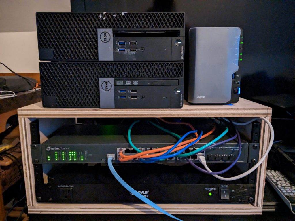
I spent a lot of time researching different hardware options that would balance cost with performance, features, expandability, and noise. My budget was $1000 (give or take a few). I ended up going with the following hardware:

  • 2x Dell Optiplex 7040 SFF desktops w/ Intel i5 CPU’s and 24GB RAM ($150 ea)
  • 2x PCIE 1GB 2-port NIC’s ($35 ea)
  • 2x USB Ethernet Adapters ($15 ea)
  • 1x Synology DS220+ (~$300 retail but I got mine for a Cyber-Monday price of $250)
  • 2x 7.2k RPM 1TB HDD’s ($50 ea)
  • 1x TP-Link tl-sg3428 Switch ($200)
  • 1x Rack-Mount Power Supply ($50)
  • 1x Home-Built Plywood Network Rack/Box (~$100)

I decided to go with the small form-factor machines rather than micro form-factor systems because of the ability to easily add NIC’s via PCIE expansion. Also, while these systems are not on VMware’s Hardware Compatability List, they do run ESXI 7.0u3 without issue (so far at least). For the switch, I was originally going to use an old HP Procurve 48G switch with some Noctua fans instead of the TP-Link, but I realized that it was pulling 50 Watts of power at idle wich equates to almost $10/mo for electricity where I live if running 24/7. The TP-Link switch uses less than 10 Watts and is quieter. At idle, the whole build only uses about 65-70 Watts and is no louder than my Precision Workstation. Finally, while I would like to go with SSD storage at some point, I decided to go with HDD’s simply because I had them and they didn’t cost me anything.

For the network configuration, each host has four network interfaces – three are standard 1Gb NIC’s plus one USB ethernet adapter. The USB ethernet adapter is used for the management network on each host as this network shouldn’t require significant bandwidth. Each of the other three NIC’s are used for the storage, vMotion, and VM traffic networks respectively (each in different vlans). While I have no NIC redundancy for any of those networks in this configuration, I plan to add another 4-port PCIE NIC in each host and configure to use two NIC’s per network. The Synology storage is exposed to via iSCSI, with both hosts connecting to the same target. With that said, I don’t have any storage redundancy – if the Synology dies my VM’s are going down.

My vCenter server is running on the dual-host cluster. Before setting up vCenter, I configured a DNS server using DNSmasq on a Debian instance on one of my ESXI hosts as hosts need to be resolvable via DNS by vCenter. I setup vCenter as a VM on that same host and then, once vCenter was up, added both hosts to a cluster in vCenter with DRS and HA enabled.

Now that I have my cluster mostly configured, it’s time to play with some of the features of vCenter. I plan to experiment with the following features and more:

  • vMotion (including Storage vMotion)
  • Host Configuration profiles
  • DRS
  • HA
  • vCenter backups
  • Distributed Swtiches

I’m planning to do another post or two covering some of the additional testing and configuration I’ll be doing of the next several weeks with my lab. I’m also going through some training on Pluralsight which covers a lot of the features of VMware virtualization so I’m hoping these resources will provide an effective platform on which to learn more about the technology. Stay tuned for more!

LoRaWAN 101 with Arduino MKRWAN 1300 and Helium – Part 2

In my last post, I showed how to connect an Arduino MKRWAN 1300 to the Helium LoRaWAN network and send a message. In this post, we’ll look at how to configure the decoder and integration functions within the Helium console to send our message data to MyDevices Cayenne.

To start, follow this tutorial from Helium to log into the MyDevices Cayenne console, add your Arduino, and then add the Helium integration within the Helium console. Next, we’ll create a Cayenne Low-Power-Protocol decoder function which will take our payload and format it in a way which Cayenne can interpret. Within the Helium console, click the “+” button to add a new function, enter a function name, and then select “Decoder” for function type and “Cayenne LPP” under “Choose Format”. Finally, to tie these pieces together, we’ll create a “Flow” to send the incoming data from the MKRWAN through the Cayenne LPP decoder function and then up to MyDevices Cayenne. You simply click and drag each node item from the “nodes” menu onto the flow area, then click and drag connectors between the node items. Below is a screenshot of how the node should be configured for reference:

With the configuration now complete, fire up your Arduino again with the code from Part 1, open the serial monitor, and send another message with a number in the message field (i.e. 30). If all is configured correctly, you should see RSSI, Temperature, and SNR data show up on the device page in the Cayenne console.

At this point, all you’d need to do to get a fully functional end-to-end (if basic) IoT solution is wire up an actual temperature sensor to your Arduino, modify the code to read the temperature sensor value and set it to the “msg” variable, and then change the function to run every minute or two on a timer. If you’re looking to report on a different environmental metric, you’d just need to change the lpp.addTemperature() function to the corresponding function for that metric (like lpp.addBarometricPressure()). You can find the functions for all the different measurement metrics here.

I really enjoyed building out this basic IoT proof-of-concept and plan to flesh this out into something more production ready. While the Cayenne platform is good, it does appear to be lacking some more advanced charting/visualization found in other platforms, so I may see if I can get this data pumped into something like ELK or Grafana. More IoT posts to come!

LoRaWAN 101 with Arduino MKRWAN 1300 and Helium – Part 1

What if you could collect data about the physical world, from almost anywhere in the world, for really short money? There’s a relatively new networking technology that enables you to do just that, called LoRaWAN. This specification defines a low power, wide area networking protocol engineered to connect wireless, battery-powered IoT devices to the internet over long distances. How long? Up to a few kilometers from the nearest gateway. The catch? This protocol only supports very low data transmission rates. However, most IoT applications don’t require a lot of bandwidth, and the tradeoff for long distance wireless communication is perfectly acceptable.

One implementation of this protocol that has taken off over the last couple of years is the Helium network. This network is made up of a distributed collection of privately owned and operated LoRaWAN gateways and network servers. The gateways, which are like wireless access points but for the LoRaWAN protocol, are actually blockchain crypto miners (in most cases). These gateways mine Helium’s HNT cryptocurrency for their operators, which is what incentivizes people to operate these gateways in the first place. You can read more about the Helium network here and see the map of over 700,000 gateways (at the time of this writing) around the world here. While there are other public and private LoRaWAN networks, most notably The Things Network, I’m currently using the Helium network simply because it has the best coverage in my area.

In part one of this two-part series of posts, I’ll show you how to join an Arduino MKRWAN 1300 microcontroller to the Helium network and send a basic message. I definitely encountered a few speed bumps trying to get it working, so I’ll touch on those as well as some important concepts you’ll need to understand if you want to try this yourself.

Prerequisites

  1. Sign into the Helium Console: This is pretty self explanatory – head over to the Helium Console and sign up. When you create your Helium account, you’ll receive an initial 10,000 credits for free. For each message you send to Helium from an end device, you’ll consume a credit. You can purchase additional credits if/when your initial 10,000 run out using a credit card under the “Data Credits” tab in the console.
  2. Make sure you are within reasonable range of a Helium Gateway: Check out the Helium Explorer to find a gateway near you. Note that if you don’t have one near you, you’ll either need to move your device closer to one or get one and configure it (I’ll cover this in my next post). Even if you are within a mile or so of a Helium Gateway, you may still run into connection issues. I’ll cover troubleshooting further down this post.

Configuring the Arduino

After unboxing, make sure to remove the black foam protective piece from the bottom end of the Arduino pins and attach the antenna. Note that not removing the foam can mess with the device communication. Walk through the first few steps outlined in this tutorial by Arduino until you have the device EUI of your MKRWAN device. With the device EUI in your clipboard, sign into the Helium console and follow this documentation to add the device.

Next, create a copy of the LoraSendAndReceive.ino example code, replace the contents with the code below, and modify the associated arduino_secrets.h file with the “SECRET_APP_EUI” and “SECRET_APP_KEY” that were generated in the Helium console for your device. This code is mostly the same as the LoraSendAndReceive.ino example with just a few modifications which I’ll outline below:

This first modification is in lines 9-12 where we import some libraries for the CayenneLPP protocol and JSON formatting. Further down the code in lines 83-87, we use those libraries to format the data we’re sending in the CayenneLPP format. This converts the message we input on the serial monitor to a CayenneLPP temperature format. In a later post, I’ll outline how we take this formatted data and send it to the Cayenne MyDevices platform for visualization. On lines 40-46, we disable all radio channels with the exception of Channel 1. I’m not sure why, but this seems to be required for the Helium network (thank you to hpssjellis on Github for outlining this here). Finally, on line 50, I set the devices to communicate as class C. The LoRaWAN protocol specifies three device class types – A, B, and C. These classes define the intervals at which the device transmits and listens. I set my device to class C for testing purposes, but do note that this setting uses much more energy than class A as it basically tells the device to listen continually. The Things Network does a great job explaining the different devices classes here.

Joining the Helium Network

Now that you’ve got the code, what should you expect when you run it? If the device is within range of a functioning Helium Gateway, the device should return “Enter a message to send to network” in the serial monitor after 30-60 seconds. If you see this, it means that a Helium server received the “Join” message via your device and the device received an “Accept” message back from Helium. In other words, the device successfully joined the Helium network. The device will perform this join handshake each time it powers on. You can see these messages in the Helium console.

If instead you see “Something went wrong; are you indoor? Move near a window and retry”, that means the join was unsuccessful. Work through these steps below to troubleshoot:

  1. Try it again… sometimes the device times out before receiving the join accept message back from network. Give it a few tries before moving on.
  2. Relocate. Start by moving your device closer to the nearest gateway if you are located more than a few hundred feet away from it. If you are less than 10 feet away from it, try moving further away – you could be too close. Finally, try moving closer to a different gateway. Some of the gateways shown in the Helium Explorer have a “This gateway is relayed…” message on them. Make sure you are not using a relayed gateway.
  3. Adjust Device Profile Settings. Within the Helium Console there is a “Profiles” tab. You can create device profiles that turn on/off ADR and set the Rx (receive) Delay. You might need to adjust these settings which you can read more about here.

If at this point you still can’t get the device to join, you may want to obtain your own gateway. I ended up purchasing a Dragino LPS-08 gateway and configuring it for the Helium network using this guide from Helium.

When prompted for a message in the Arduino IDE serial monitor, enter a number (i.e. 20) and hit enter. You should then see two new device messages in Helium console – “Uplink” and “Acknowledge”. The “Uplink” message is what contains your “payload”, which in this case is the CayenneLPP-formatted message you typed in the serial monitor.

You should see these four messages after a successful join and message uplink.

In Part 2 of this series, I’ll show you how we configure a decoder for the CayenneLPP protocol and send it to MyDevices Cayenne for visualization. Stay tuned!